Hardware Extensions
Overview
Kobuki provides additional Power connections and an Expansion Port with analog & digital io (and additional power connections) that let you extend the capabilities of your Kobuki in wierd and wonderful ways. Refer to those links for specific details.
Some interesting examples to follow.
Use Case - Payload Balancing
Note
Kobuki’s ancestry belongs to cleaning robot lines and consequently wasn’t designed for handling variations in payload. Sometimes you’ll need to provide some assistance!
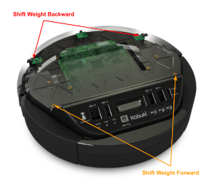
When you start mounting additional equipment on Kobuki, the kinematic and dynamic motion envelopes will start to be considerably affected as the centre of gravity shifts. This is particularly important when it comes to Kobuki’s ability to traverse small obstacles or slopes as it travels in the longitudinal direction.
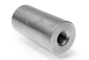
In these cases, simply design some weights that can be mounted, like ballast, to shift the centre of gravity to where you need it. An example of such were the metal cylindrical pipes designed for the Turtlebot 2. These could be affixed around poles attached to the screws on the back of the kobuki.
|
|
| Steel Anchor Weights | Placement |
Use Case - 3D Sensor
Depth sensors are typically connected to the 12V 1.5A power supply and via USB to your compute board (netbook/embedded board). To do this you’ll need to modify the power capable with the connector specified in the Power section.
Todo
Could really use a step-by-step pictorial walkthrough.
Use Case - Laptop Recharging
Note
Recharging mode will only activate when the Kobuki itself is being recharged (otherwise the current draw would have a detrimental affect on runtime performance). This is true for both dock / cable recharging.
Similar to the depth sensor use case, you’ll need to modify the recharging cable for a netbook and attach it to the 19V@2A connector (refer to the Power section) to take advantage of the on-board power supply. This is not only extremely convenient (no more detaching/reattaching) but will also permit you to completely automate your application.
Most turtlebot 2 suppliers would provide a netbook / modified cable with the full solution.
Todo
Could really use a step-by-step pictorial walkthrough.
Use Case - IR Sensor Array
Kobuki usually gets equipped with a 3d sensor, however, these typically have limitations for the purposes of obstacle avoidance:
- Narrow fov (58° x 43° horizontal x vertical)
- Death zone in the first 45 cm
- Cannot detect glass walls
- Cannot reliably detect polished metallic or very black surfaces
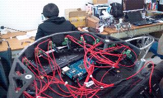
In one experiment an 11 IR sensors half ring, pointing 12 degrees downward was added to compensate.
- Sensor model: Sharp GP2Y0A21YK
- Power supply: Kobuki’s 5V, 1A
- Sensor reading: Arduino MEGA 2560
- PC interface: Arduino custom firmware – Bosch adc_driver
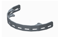
- Mounting: 3D printed frame.
|
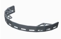
|
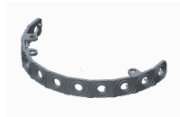
|
| PSD Array I | PSD Array II | Sonar Array |
The analog output of sensors is read by the Arduino board, while for power and ground they are connected to Kobuki’s 5V 1A power source. Connecting several sensors to the same power supply makes readings very noisy when there aren’t obstacles. The solution was to put decoupling capacitors on each sensor. For interfacing Arduino, we use Bosch adc_driver.
Different mounting frames are available for downloading and printing in our file server:
- Horizontally mounted MaxBotix’s LV-Maxsonars
- Horizontally mounted Sharp IR sensors
- 12 degrees downward pointing Sharp IR sensors